Tiny/v2.11

The complete re-design of the popular Tiny autopilot was done on October 9, 2007. The new design is not a bug-fix as no known flaws exist with the current 0.99 and 1.1 versions, so the redesign is performance, easy to use and easy to assemble-oriented !
Hardware Revision History
| Version # | Release Date | Release Notes |
|---|---|---|
| v2.11 | 12/2007 | Bug fix : GPS Reset pin protection (D2) |
| v2.1 | 10/2007 | 3.3V regulator type changed, power switch type changed, connectivity improved |
| v2.0 | 06/2007 | Initial release of Tiny v2 |
Features
- Single LPC2148 MCU
- 8 x Analog input channels 0V - 3.3V (2 channels with optional on-board resistor bridge)
- 1 x 3.3V TTL UART (5V tolerant)
- 8 x PWM outputs
- 1 x R/C receiver PPM frame input
- 1 x SPI bus
- 1 x I2C bus
- 1 x USB (client)
- Integrated GPS receiver and patch antenna (4Hz update)
- 5v / 2.25A switching power supply (input voltage range 6.1v → 18v)
- 3.3v / 1A linear regulator
- 3 x status LEDs with attached test point
- 24 grams (with LEA-4P GPS and 18mm GPS antenna)
- 70.8 x 40mm (smaller then a banking card)
- 2 layers PCB design, 0603 components
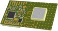
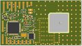
Tiny v2.1 3D top view (18mm GPS antenna)
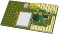
Tiny v2.1 3D bottom view
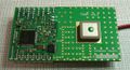
Tiny v2.1 top side view (13mm GPS antenna)
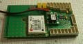
Tiny v2.1 bottom side view


The Tiny v2.1 autopilot uses a single Philips LPC2148 ARM7 based microcontroller. The ARM7 is a low-power 32-bit RISC processor core and the Philips LPC2148 has 512KB on-chip Flash ROM, 40KB RAM and can be clocked at 60MHz.
Although critical control code such as the R/C interface and servo output are well segregated in Paparazzi software and well protected from interference from flaws in the stability/navigation/comm/payload code, great care must be taken when experimenting with new software as some errors can cause a the processor to halt or stall for extended periods causing total loss of control.
Feature additions : Tiny 2.1 vs Tiny 1.1
- Hardware flow control on the modem
- The LPC has one "full-featured" serial port and one basic serial port.
- Tiny v1.1 had the full-featured port hard-wired to the GPS in order to leave the basic port open for initial bootloader programming.
- Tiny v2.1 exchange these ports and use the GPS Reset signal to "disconnect" the GPS for the one-time bootloader programming. Hardware flow control on the modem is now possible.
- 5V switching power supply
- The Texas Instruments PTH08080WAH switching 5V/2.25A integrated power supply module greatly simplify manufacturing, reduce costs, and improve performance.
- Tiny v2.1 have a voltage input range of 6.1V → 18V and enough 5V power for servos, high-power modems and video systems. Be careful using high power or digital servos consuming a lot of current. If you use four or more of them on your airframe it is recommended to supply them separately.
- 3.3V linear regulator
- Tiny v2.1 use a LM3940 1A regulator for 5V to 3.3V conversion in a SOT223 standard pinout package which is capable of providing plenty of power to modems or other devices.
- Tests have shown that any device with irregular power consumption can cause significant voltage fluctuations on the critical 3.3V bus.
- Users are advised to use a separate regulator as needed for such devices.
- Video/payload power switch.
- The TPS1100 transistor used on the Tiny v1.1 design has proven extremely useful but is intended for high-speed power switching of motor controllers and occupies a 5mm x 6mm space (SOIC-8).
- The replacement on the new Tiny v2.1 is a current-limiting switch TPS2051B intended for peripheral power control and should protect the 5V supply from voltage sags during the power-up of high capacitance peripherals as well as allow the 5V supply to continue working in the event of a complete short-circuit in the payload.
- TPS2051BDBVR Single 500mA (1A limited) switch in a 3mm x 3mm SOT23-5 package
- GPS ground plane and antenna
- The 13mm antenna on previous Tiny v1.1 proved to be an unworthy exchange of performance for weight. Crude parking-lot tests showed an approximate 3dBi loss (as expected from the data sheets), but the narrow bandwidth of the small antenna made it more sensitive to de-tuning from nearby components in the aircraft. Flight performance was acceptable but poor climb rate calculations were observed with the smaller antenna. Tiny 1.1 users are advised to fit a 20mm antenna.
- Tiny v2.1 use a 18mm x 4mm antenna (20mm x 4mm is possible but no more available) and feature 30% more ground plane area (40 x 40mm).
- GPS Reset
- Occasionally the GPS fails to boot properly, displays very poor S/N ratios, and fails to obtain a valid fix. This may be caused by a slow power-up of the 5V or 3V regulators, or by some unusual EMI that is only present at boot. Usually a simple power cycle will correct the problem but occasionally the receiver seems to use the backup battery to retain the bad state.
- On the Tiny v2.1 design GPS reset is connected to a GPIO pin on the MCU and allow the operator to reset the GPS as needed.
- Headers
- Tiny v2.1 feature revised header layouts on all peripherals.
- The modem header have CTS/RTS/DTR and both 5V and 3.3V supplies.(3.3V is shared with LPC and ADC channels - use with caution and only with very low power modems like the 10mW Xbee).
- The Tiny v1.1 button is removed and it's function is combined on the USB header along with a LED trigger so that indicator, button, and USB can be remotely mounted.
- Vertical Infrared (1 ADC) with 3.3v supply
- Horizontal Infrared (2 ADC) with 3.3v supply
- 2 general purpose ADC with both 3.3v and 5v supplies
- 2 general purpose ADC with optional on-board resistor bridge and both 3.3v and 5v supplies
- Two axis Camera control with two servo signal, vdo switch control, vdo power switch and both 5V and 3.3V supplies
- SPI bus with 3.3V supply
- I2C bus with both 5V and 3V supplies
- Leds & testpoints
- 3 status LEDs with attached test point available on Tiny v2.1 design (instead 2 on Tiny v1.1)
- Components size
- Many users (not only beginners) don't really think that 0402 components on Tiny v1.1 is a great saving from any viewpoint. Even if one saves a little space by using these components, there must still be enough room around to solder it by hand with a soldering iron.
- Tiny v2.1 use 0603 components, the assembly should be a bit more friendly to everyone.
- Layers amount
- Tiny v2.1 2 Layer design (instead 4 Layers on Tiny v1.1) should simplify manufacturing and reduce costs.
Architecture

Pinout
Pins Name and Type are specified with respect to the Autopilot Board

| Pin # | Name | Type | Description | Suggested Color |
|---|---|---|---|---|
| 1 | GND | PWR | common ground | Black |
| 2 | +5V | PWR | 5V Rail from Tiny | Orange |
| 3 | +3.3V | PWR | 3.3V Rail from Tiny | Red |
| 4 | DTR | |||
| 5 | CTS | |||
| 6 | RTS | |||
| 7 | RXD1 | IN | UART1 Serial Input (3.3V level, 5V Tolerant) | Green |
| 8 | TXD1 | OUT | UART1 Serial Output (3.3V level) | Blue |
| Pin # | Name | Type | Description | Suggested Color |
|---|---|---|---|---|
| 1 | GND | PWR | common ground | Black |
| 2 | +3.3V | PWR | 3.3V Rail from Tiny | Red |
| 3 | SSEL | IN | SSP Slave Select. Selects the SSP interface as a slave (SSEL1) | Brown |
| 4 | MOSI | I/O | SPI1 Master Out Slave In. Data output from master or data input to slave | Grey |
| 5 | MISO | I/O | SPI1 Master In Slave Out. Data input to master or data output from slave | Green |
| 6 | DRDY | IN | External interrupt 0 input (EINT0) | Purple |
| 7 | SCK | I/O | SPI0 Serial clock. Clock output from master or input to slave | Yellow |
| Pin # | Name | Type | Description | Suggested Color |
|---|---|---|---|---|
| 1 | GND | PWR | common ground | Black |
| 2 | +5v | PWR | 5V Rail from Tiny to R/C receiver supply | Orange |
| 3 | PPM_IN | IN | PPM Stream from R/C Receiver (5V tolerant) | White |
| 4 | SERV_RST | OUT | external PPM decoder reset (Note 1) | |
| 5 | SERV_CLK | OUT | external PPM decoder clock (Note 1) |
Note 1 : Used only if servos are connected to the R/C receiver
| Pin # | Name | Type | Description | Suggested Color |
|---|---|---|---|---|
| 1 | GND | PWR | common ground | Black |
| 2 | +3.3V | PWR | 3.3V Rail from Tiny | Red |
| 3 | USB+ | I/O | USB bidirectional D+ line | Green |
| 4 | USB- | I/O | USB bidirectional D- line | White |
| 5 | VBUS | IN | Indicates the presence of USB bus power (P0.23) (5V level) | Orange |
| 6 | BUTTON | IN | External Button (+3.3v pullup) | |
| 7 | LED3 | OUT | GPIO (LED #3 command) | |
| 8 | ADC_7 | IN | Analog to Digital Converter Input #7 |
| Pin # | Name | Type | Description | Suggested Color |
|---|---|---|---|---|
| 1 | GND | PWR | common ground | Black |
| 2 | +3.3V | PWR | 3.3V Rail from Tiny | Red |
| 3 | IRV | IN | Vertical IR Sensor signal (Analog to Digital Converter Input #0) | Purple |
| Pin # | Name | Type | Description | Suggested Color |
|---|---|---|---|---|
| 1 | GND | PWR | common ground | Black |
| 2 | +3.3V | PWR | 3.3V Rail from Tiny | Red |
| 3 | IRH_2 | IN | Horizontal IR Sensor signal axis 2 (Analog to Digital Converter Input #2) | Grey |
| 4 | IRH_1 | IN | Horizontal IR Sensor signal axis 1 (Analog to Digital Converter Input #1) | Brown |
| Pin # | Name | Type | Description | Suggested Color |
|---|---|---|---|---|
| 1 | GND | PWR | common ground | Black |
| 2 | +5v | PWR | 5V Rail from Tiny | Orange |
| 3 | +3.3V | PWR | 3.3V Rail from Tiny | Red |
| 4 | ADC_4 | IN | Analog to Digital Converter Input #4 | |
| 5 | ADC_3 | IN | Analog to Digital Converter Input #3 |
| Pin # | Name | Type | Description | Suggested Color |
|---|---|---|---|---|
| 1 | GND | PWR | common ground | Black |
| 2 | +5v | PWR | 5V Rail from Tiny | Orange |
| 3 | +3.3V | PWR | 3.3V Rail from Tiny | Red |
| 4 | ADC_6 | IN | Analog to Digital Converter Input #6 (Maximum input level can be selected with R12 value) | |
| 5 | ADC_5 | IN | Analog to Digital Converter Input #5 (Maximum input level can be selected with R13 value) |
| Pin # | Name | Type | Description | Suggested Color |
|---|---|---|---|---|
| 1 | GND | PWR | common ground | Black |
| 2 | +5v | PWR | 5V Rail from Tiny | Orange |
| 3 | +3.3V | PWR | 3.3V Rail from Tiny | Red |
| 4 | BOOT | IN | In-Circuit Serial Programming (ISP) enable (P0.14, +3.3v pullup) (Note 2) | |
| 5 | GPS_RESET | IN | leave unconnected, hold this pin low only for bootloader programming | |
| 6 | TXD0 | OUT | UART0 Serial Output (shared with GPS receiver) | Blue |
| 7 | RXD0 | IN | UART0 Serial Input (shared with GPS receiver) | Green |
Note 2 : Holding this pin low for at least 3mS after a RESET (or power up) instructs the controller to enter programming mode.
| Pin # | Name | Type | Description | Suggested Color |
|---|---|---|---|---|
| 1 | GND | PWR | common ground | Black |
| 2 | +5V | PWR | 5V Rail from Tiny | Orange |
| 3 | +3.3V | PWR | 3.3V Rail from Tiny | Red |
| 4 | SDA | I/O | I2C bus Serial DAta | |
| 5 | SCL | I/O | I2C bus Serial CLock |
| Pin # | Name | Type | Description | Suggested Color |
|---|---|---|---|---|
| 1 | GND | PWR | common ground | Black |
| 2 | +5V | PWR | 5V Rail from Tiny | Orange |
| 3 | +3.3V | PWR | 3.3V Rail from Tiny | Red |
| 4 | CAM_SW | OUT | video source/payload selection signal | |
| 5 | SRV_1 | OUT | Servo PWM signal #1 | |
| 6 | SRV_5 | OUT | Servo PWM signal #5 | |
| 7 | AUX | PWR | video/payload switchable 5V power suply |
LEDs
Tiny 2.1 has 3 LEDs. By default the LEDs are use for:
- LED 1, green
- not used by default
- LED 2, red
- GPS_LED: blinking if trying to get a fix, on if 3D fix
- LED 3, yellow
- not used by default
Schematic

PCB
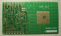
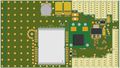
Tiny v2.1 PCB top side view (Olimex)
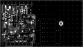
Tiny v2.11 PCB top copper
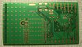
Tiny v2.1 PCB bottom side view (Olimex)
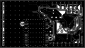
Tiny v2.11 PCB bottom copper


Gerber & Drill Files
Download Tiny v2.11 gerber & drill files (zip)
RS274X, units = Inches, format = 2:5
- Tiny_v2-11.GTO (Top Component Print Layer)
- Tiny_v2-11.GTS (Top Solder Mask)
- Tiny_v2-11.GTL (Top Copper Layer)
- Tiny_v2-11.GBL (Bottom Copper Layer)
- Tiny_v2-11.GBS (Bottom Solder Mask)
- Tiny_v2-11.DRI (NC XY coordinates & Drill tools sizes)
Assembly
Have a look at the Tiny_Assembly for assembly hints.
Components Layout
Tiny v2.11 top components Layout
Tiny v2.11 bottom components Layout
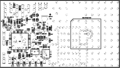
Tiny v2.11 top components details
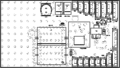
Tiny v2.11 bottom components details


Bill Of Material
Download Tiny v2.11 Bill Of Material (zipped .xls file)
| Qty | Manufacturer part # | Schematic part name / value | Designator | Description | Manufacturer | Package | Optional | Digikey.com | Other distributor |
|---|---|---|---|---|---|---|---|---|---|
| Resistors | |||||||||
| 2 | ERJ-3EKF33R0V | 33 | R21, R22 | 1/16W, 5% | Panasonic | 0603 | P33HCT-ND | ||
| 2 | ERJ-3EKF1000V | 100 | R5, R24 | 1/16W, 5% | Panasonic | 0603 | P100HCT-ND | ||
| 1 | ERJ-3EKF3300V | 330 | R4 | 1/16W, 5% | Panasonic | 0603 | P330HCT-ND | ||
| 3 | ERJ-3EKF1001V | 1K | R16, R17, R23 | 1/16W, 5% | Panasonic | 0603 | P1.00KHCT-ND | ||
| 3 | ERJ-3EKF1501V | 1.5K | R2, R19, R20 | 1/16W, 5% | Panasonic | 0603 | P1.50KHCT-ND | ||
| 2 | ERJ-3EKF1801V | 1.8k (see note1) | R13,R18 | 1/16W, 5% | Panasonic | 0603 | P1.8KHCT-ND | ||
| 3 | ERJ-3EKF3301V | 3.3K | R3, R14, R15 | 1/16W, 5% | Panasonic | 0603 | P3.3KHCT-ND | ||
| 7 | ERJ-3EKF1002V | 10K | R1, R6 to R11 | 1/16W, 5% | Panasonic | 0603 | P10.0KHCT-ND | ||
| 1 | ERJ-3EKF1502V | 15K (see note2) | R12 | 1/16W, 5% | Panasonic | 0603 | P15.0KHCT-ND | ||
| Capacitors | |||||||||
| 5 | C0603C180J5GAC | 18pF | C22, C26 to C29 | 50V, 5% | Kemet | 0603 | 399-1052-1-ND | ||
| 19 | C0603C104K5RAC | 100nF | C2 to C20 | 50V, 10% | Kemet | 0603 | 399-5089-1-ND | ||
| 2 | T520A336M006ATE070 | 33uF/6V | C24, C25 | SMD tantalum capacitor | Kemet | A case (EIA 3216-18) | 399-4719-1-ND | ||
| 2 | TAJD107K020R | 100uF/20V | C1, C21 | SMD tantalum capacitor | AVX Corp. | D case (EIA 7343-31) | 478-1724-1-ND | ||
| 1 | EEC-EN0F204J2 | 0.2F | C23 | SMD double layer capacitor (Goldcap) | Panasonic | specific | P14163CT-ND | ||
| Inductors | |||||||||
| 1 | MLF2012DR47K | 0.47uH | L1 | SMD Inductor | TDK | 0805 | 445-1043-1-ND | ||
| Semiconductors | |||||||||
| 2 | 1PS79SB10 | 1PS79SB10 | D1, D2 | Schottky diode 0.2A/30v | NXP | SOD523 (EIA SC79) | 1PS79SB10 T/R-ND | ||
| 1 | LM3940IMP-3.3 | LM3940IMP-3.3 | IC3 | 1A low dropout regulator for 5V to 3.3V conversion | National Semic. | SOT223 | LM3940IMP-3.3CT-ND | ||
| 1 | TPS2051BDBV | TPS2051B | IC4 | Current Limited Power Distribution Switch | Texas Instr. | SOT23-5 | yes | 296-21265-1-ND | |
| 1 | LPC2148FBD64 | LPC2148FBD64 | IC5 | Single-chip ARM7 32-bit microcontroller | NXP | LQFP64 | 568-1765-ND | ||
| 1 | CD4017BPW | 4017 | IC6 | Decade Counter/Divider with 10 Decoded Outputs | Texas Instr. | TSSOP16 | 296-14252-1-ND | ||
| 1 | APT1608MGC | KP-1608MGC | LED1 | SMD Chip Green LED Lamp | Kingbright | 0603 | 754-1118-1-ND | ||
| 1 | APT1608SURCK | KP-1608SURC | LED2 | SMD Chip Red LED Lamp | Kingbright | 0603 | yes | 754-1123-1-ND | |
| 1 | APT1608SYCK | KP-1608SYC | LED3 | SMD Chip Yellow LED Lamp | Kingbright | 0603 | yes | 754-1124-1-ND | |
| 1 | BC807-40 | BC807 | T1 | PNP general purpose transistor | NXP | SOT23 | 568-1629-1-ND | ||
| Modules | |||||||||
| 1 | PTH08080WAH | PTH_08080W | IC1 | Wide-input adjustable switching regulator | Texas Instr. | specific | 296-20432-ND | ||
| 1 | LEA-4P-0-000-0 | LEA_4P | IC2 | GPS receiver | ublox | specific | N/A | (u-blox.com, see note 3) | |
| Connectors | |||||||||
| 7 | 53047-0310 | SRV0, SRV4, SRV2, SRV6, IRV, SRV3, SRV7 | J12 to J18 | Picoblade 3 pins 1.25mm straight header | Molex | specific | WM1732-ND | ||
| 1 | 53047-0410 | IRH | J11 | Picoblade 4 pins 1.25mm straight header | Molex | specific | WM1733-ND | ||
| 4 | 53047-0510 | PPM,I2C,ADC2,ADC1 | J4, J6, J8, J10 | Picoblade 5 pins 1.25mm straight header | Molex | specific | J6,J8,J10 | WM1734-ND | |
| 3 | 53047-0710 | SPI,CAM,DOWNLOAD | J3, J5, J7 | Picoblade 7 pins 1.25mm straight header | Molex | specific | J3,J5 | WM1736-ND | |
| 2 | 53047-0810 | SERIAL,USB | J2, J9 | Picoblade 8 pins 1.25mm straight header | Molex | specific | WM1737-ND | ||
| Other | |||||||||
| 1 | 405C35B12M00000 | CTS405 12MHz | Q1 | SMD 12MHz Quartz Crystal | CTS | specific | CTX639CT-ND | ||
| 1 | KSA-ST1580MS18 | KSA-ST1580MS18 | A1 | 18x18mm ceramic Patch Antenna | Sangshin | specific | - | N/A | KSA-ST1580MS18 (rfmw.com) |
| ANA1580T18D4 | Emtac | ANA1580T18D4 (transplantgps.com) | |||||||
Note 1 :
R13 calculated according attached ADC5 desired input level :
- 3.3v ⇒ 0
- 5v ⇒ 1.8k (default)
- 8v ⇒ 4.7k
- 13v ⇒ 10k
- 18v ⇒ 15K
- Other ⇒ R13 = (Vin - 3.3) x 1000
Note 2 : R12 calculated according attached ADC6 desired input level :
- 3.3v ⇒ 0
- 5v ⇒ 1.8k
- 8v ⇒ 4.7k
- 13v ⇒ 10k
- 18v ⇒ 15K (default)
- Other ⇒ R13 = (Vin - 3.3) x 1000
Note 3 : For sales make contact with Ublox distributor in the appropriate region (http://www.u-blox.com/disti/index.html) Remark: u-blox are strictly controlling their GPS Chips right now, for some reason! They will refer you to get one on their website, which is $99.
PCB and assembled boards suppliers
For private companies and enthusiast Paparazzi hardware suppliers, see Get Hardware page.
Downloads
Source files
Gerber & Drill files
Assembly files
Programming

The Philips LPC21xx series ARM7 microcontrollers include hardware ISP (InCircuit Serial Programming) and can be programmed through the serial interface UART0 (labled "download" on the PCB) by holding pin P0.14 (count 4 pins in from outside of PCB on download connector) low during power-up and until USB boot code programming is completed. Note this is a 1x operation usually done by the person supplying the Tiny v2 autopilot so you may want to ask if this was done from your Tiny v2 vendor.
Once the USB boot code is loaded (see above) the Paparazzi software includes a USB bootloader program that allows for easy 1-second programming through a standard USB port (labeled "USB" on the PCB) with only a USB to Tiny Molex 8-pin adapter cable needed. Using either the GUI (paparazzi) or command line arguments you can now upload new settings, flight plans, or software updates quickly and conveniently.
See the FirmwareFlashing page for more detailed instructions on installing the bootloader and autopilot software.